


PENSTOCK / SLUICE GATE AND WATER GATES APPLICATION
Penstock or commonly known as Sluice Gate is an intake structure that control the water flow and designed to be sturdy as the high pressurize water flow are passes through it. The term of Penstock is inherited from the earlier technology used in watermills. The amount of water that is allowed to flow through the penstock can be controlled with a sluice, which is simply a gate that can be raised and lowered to increase or decrease the amount of water allowed to flow through. When the sluice is fully open, water flows freely down through the penstock. However, when it is closed slightly there is a limitation to how much water can flow, and thus less water enters the penstock. It is important to be able to control the amount of water that can enter the penstock for a number of reasons, mainly because it allows people to regulate the amount of water that exits the penstocks at the other end. During dry seasons, penstocks are generally allowed to be wide open to allow water through, while they are closed partially during wet seasons to prevent flooding.
In Malaysia, Penstock are widely used in variety of water and waste water work application as water as water and sewage treatment project and flood control projects.
Below are Listed some of the types of Penstock & Water Gates that supplied and distributed by Mirolxtec :-
Wall-Mounted Penstock
 |
 |
 |
Wall-Mounted Penstock is the most common and widely used of penstock in both water and waste water works application in Malaysia and around the world. Lecotech Wall-Mounted Penstock is fabricated with Stainless Steel in BS 7775 / AWWA C561 specification standard. The penstock can be equipped with rising or non-rising stem option and can be used for on seating and off seating water pressure direction. Lecotech offers the sizes from 150mm x 150mm until 1200mm x 1200mm for Wall-Mounted Penstock.
This type is also have a unique self-adjusting seal design that can achieve minimal equal seating and unseating (bidirectional) leakage rates, for sizes of 1300mm x 1300mm up to 4000mm x 4000mm are also available in bidirectional configurations. The maximum leakage rate is lower than the maximum allowed recommended by BS 7775 Standard under normal conditions.

Channel-Mounted Penstock
 |
 |
 |
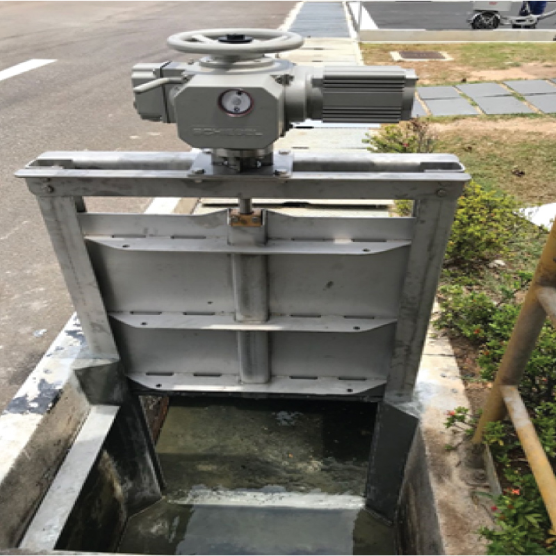
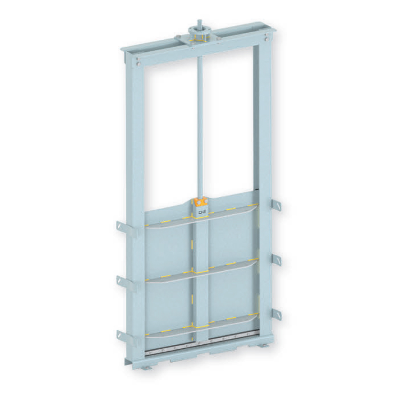
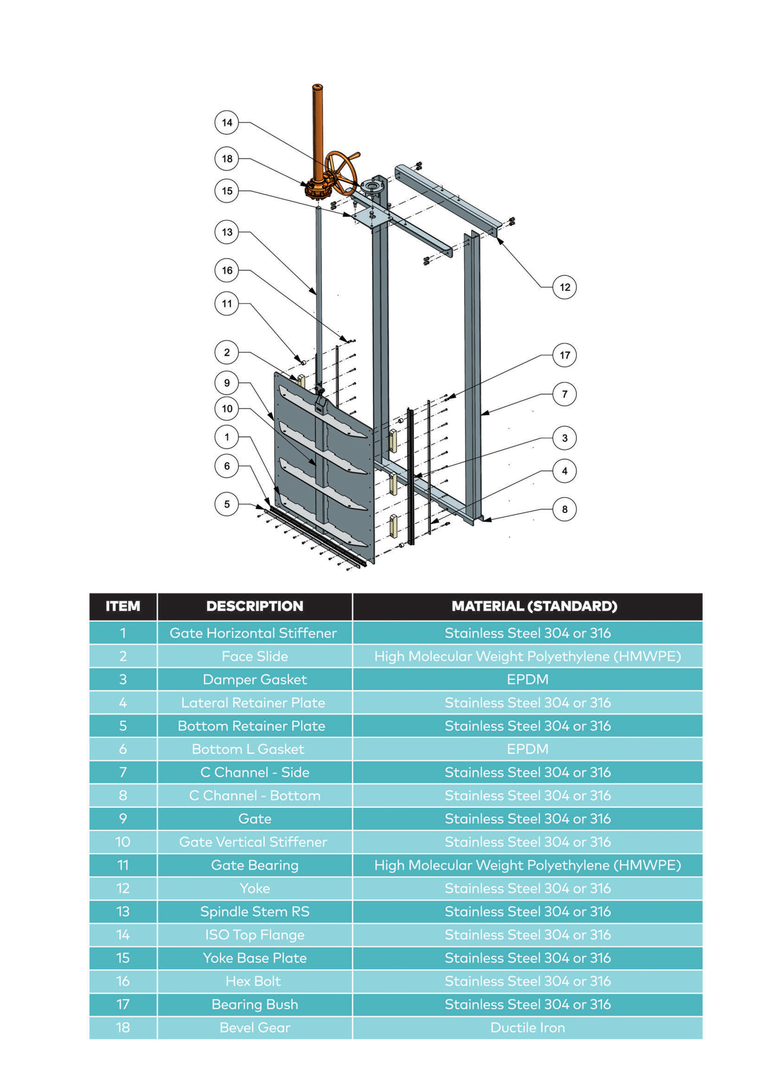
Channel Mounted Gate (CM) is designed for open channel installation with a highly versatile flow control in waste water treatment plants, irrigation, hydraulic works and hydro-electric power plants. It is used for channel water flow direction or water distribution control purpose and allows to overflow on top of the gate. Technically the water head design for the Channel Penstock shall follow the height of the gate. However, higher water head can be designed upon request.
The sealing system is incoporated on both laterals and bottom area of the slide, resulting in a perfect seal without the need of wedges on the gate. From sizes 150MM X 150MM to 2000MM X 2000MM, the Penstock has a unique seal design for applications requiring accurate flow regulation and optimum performance. The maximum allowable recommended by BS 7775 Standards under normal conditions. Penstock can be used in on and off seating with rising and non-rising stem optional. All the sealing surface and the assembly hardware is built using the Anti-Corrosion Materials. Lecotech’s Channel Mounted Penstock is available in 4 Sides Seating faces and the allowable leakage rate is fulfill the BS7775 Standards
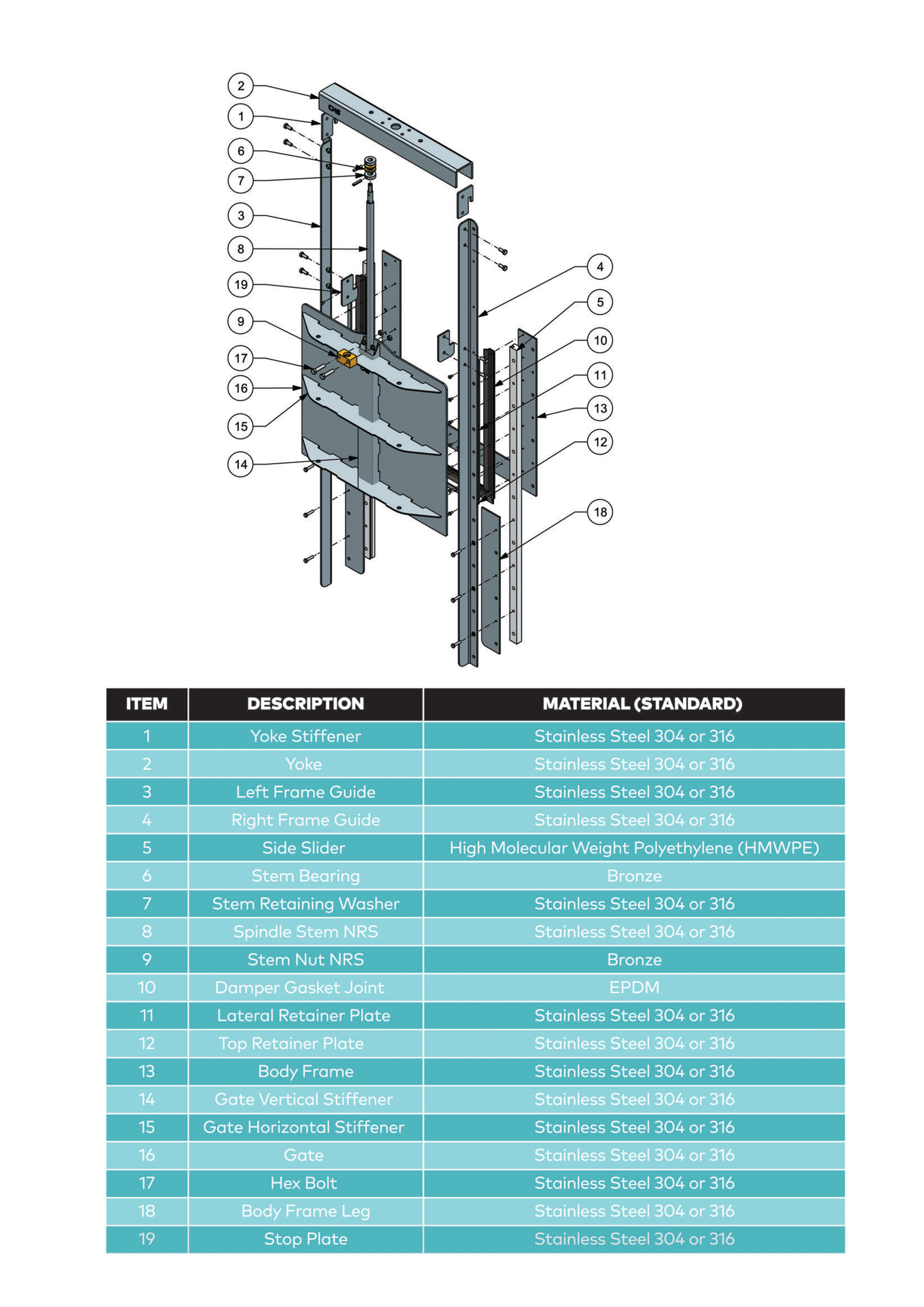
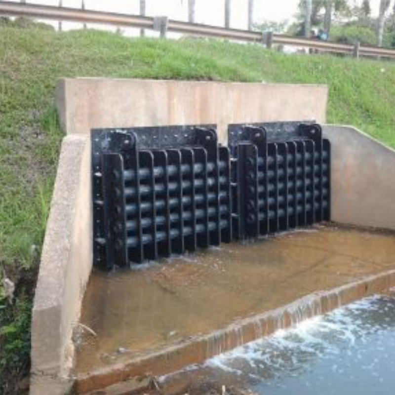
Weir Gate – Downward Opening Penstock

The Weir Gate Penstock is designed for downward opening application where a more accurate flow control are needed. It is also can be used in Water Distribution, Drainage and other places where Flow and Level Controlling mechanisms are required. The Water flows over the top of the slide permitting a constant upstream water elevation. The Weir Gate is available from the ranges of 150mm x 150mm up to 2000mm x 2000mm.
The sealing system in incorporated on 3 sides (Both laterals and bottom), resulting in a substantially watertight seal without the need of wedges on the gate. This unique design achieves Bidirectional performances (seating and unseating pressure conditions). Additionally, a 4 sides sealing system to BS7775 standard is available upon request.
HDPE FLAP GATE
LecoTech Flap Gate is made of exceptionally strong & tough High Density Polyethylene (HDPE) Pipe and Sheet. A small differential pressure on the back of the gate causes it to open automatically to allow discharge through levees, sewer lines or drainage conduits. When water on the face side of the gate rises above water on the back side, the gate closes automatically to prevent backflow. Flap gates are equipped with flat-back seats for attaching to wall thimbles, headwalls, and existing pipe flanges. The seat or frame of the flap gate is attached to a wall or pipe flange and forms the opening through which water passes.
Rectangle Wall-Mounted HDPE Flap Gate |
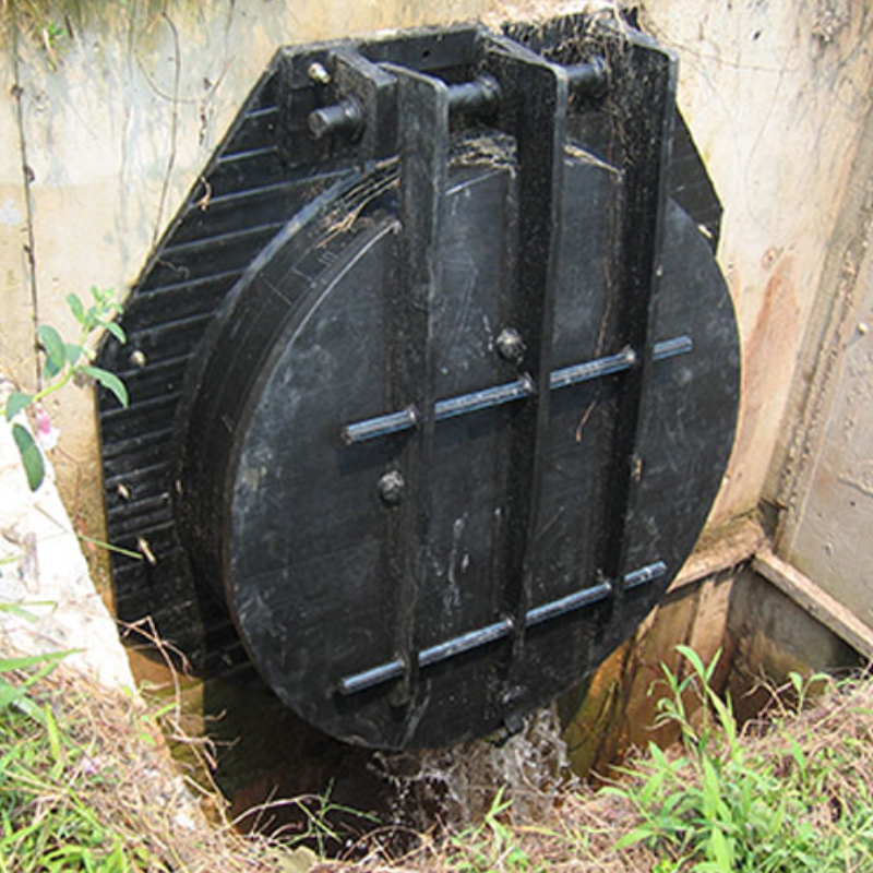
Round Wall-Mounted HDPE Flap Gate |
Applications for HDPE Flap Gate
The HDPE Flap Gate are used for variety of Water application such as :-
- Flood Control
- Municipal Projects
- Farm Leeves
- Sewer Outfalls
- Industrial waste lines
- Water and Sewage Treatment Plants
- Tidal Drainage
- Irrigation Systems
- Pump Discharge control
Product Specification Table
| General Characteristic | Value |
| Density | 0.95 g/cm3 |
| Melting Temperature | 125 – 130 °C |
| Distortion Temperature | 130 – 140 °C |
| Vicat-B Temperature | 70 °C |
| Glass Transition Temperature | 110 °C |
| Water Absorption | 0 % |
| Physical Characteristic Application Temperature | -50 – +85 °C |
| Thermal Conduction Coefficient at 20°C | 0.43 W/mK |
| Linear Expansion Coefficient | 150 – 300 103/K |
| Mechanical Characteristic Tensile Strenght | 22 N/mm2 |
| Elongation on Breaking | 15 % |
| Elongation / Breaking Ratio | > 800 % |
| Bending Strength | 10 – 40 N/mm2 |
| Elasticity Modulus under Tension | 150 – 800 N/mm2 |
| Hardness | 63 Shore-D |
| Ball Thrust Hardness | 40 – 80 Mpa |
| Notched-Bar Impact Test | 12 kJ/m2 |
| Chemical Resistance | |
| Organic Acid | resistant |
| Inorganic Acid | resistant |
| Oxidizing Acid | partially resistant |
| Bases | resistant |
| Alcohols | resistant |
| Ketones | resistant |
| Aliphatic Compounds | resistant |
| Aromatic Compounds | partially resistant |
| Trichoroethylene | partially resistant |
HDPE Flap Gate Available at Mirolxtec :-
- Lecotech HDPE Flap Gate (Round)
- Lecotech HDPE Flap Gate (Square)
- Spirolite HDPE Flap Gate
STOPLOG
The Lecotech Stoplog is designed for open channel installations for temporary isolation and flow control. Stoplogs are ideal for maintenance and repair works or flood control and diversion. The stoplog is designed to be easy to handle and deploy, without compromising safety or durability. The Logs are stacked on top of each other in the frame guides. The water level is controlled by adding or removing logs. The sealing system is bidirectional (suitable for flows in either direction) and allows to achieve very low leakages rates.
The frame can be made of mild steel or stainless steel and it can be designed to be embedded in concrete, wall mount or face mounted in a existing channel.
Mild Steel Stoplog applicable for :-
- Hot Dip Galvanize
- Epoxy Coating
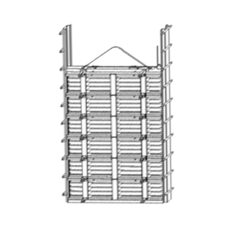
Stainless Steel Stoplog |

Stainless Steel Single Plate Stoplog |
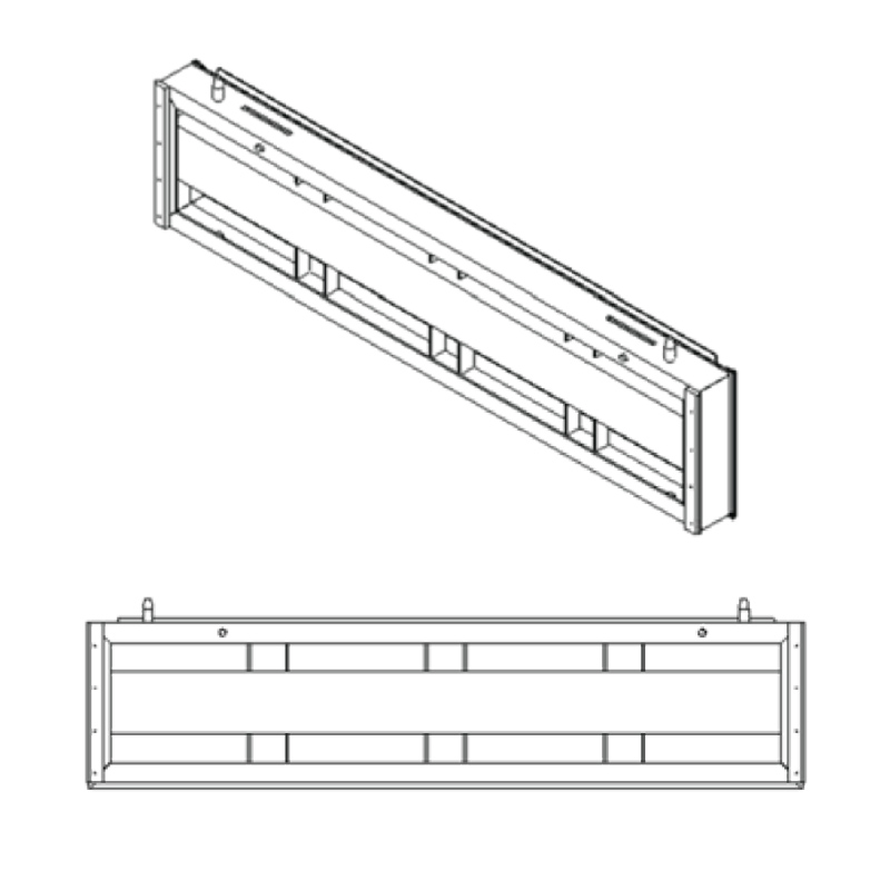
Stainless Steel Stoplog Panel |
Stoplog Design Features
Stoplog Panel Design :-
- LecoTech panel for easy handling
- Stackable Panels : Water level can be controlled by adding or removing logs.
- Two Different Panels (Mild Steel & Stainless Steel) available to always find a solution to specific requirements.
Stoplog Sealing System :-
- Single direction self adjusting seal to control flow in single direction.
- Excellent tightness
- Vertical seals are placed on the frame guides. horizontal seals are placed at the top of each panels to prevent leak between logs.
- HMWPE Guides are placed on the frame guides to assure no metal-to-metal contact between the frame and the logs, which reduce friction during operation and extends seal life.
Stoplog Frame Design :-
- Mild Steel or Stainless Steel Frame Guides.
- Mounting Options : embedded in concrete, wall mounted in existing channel.
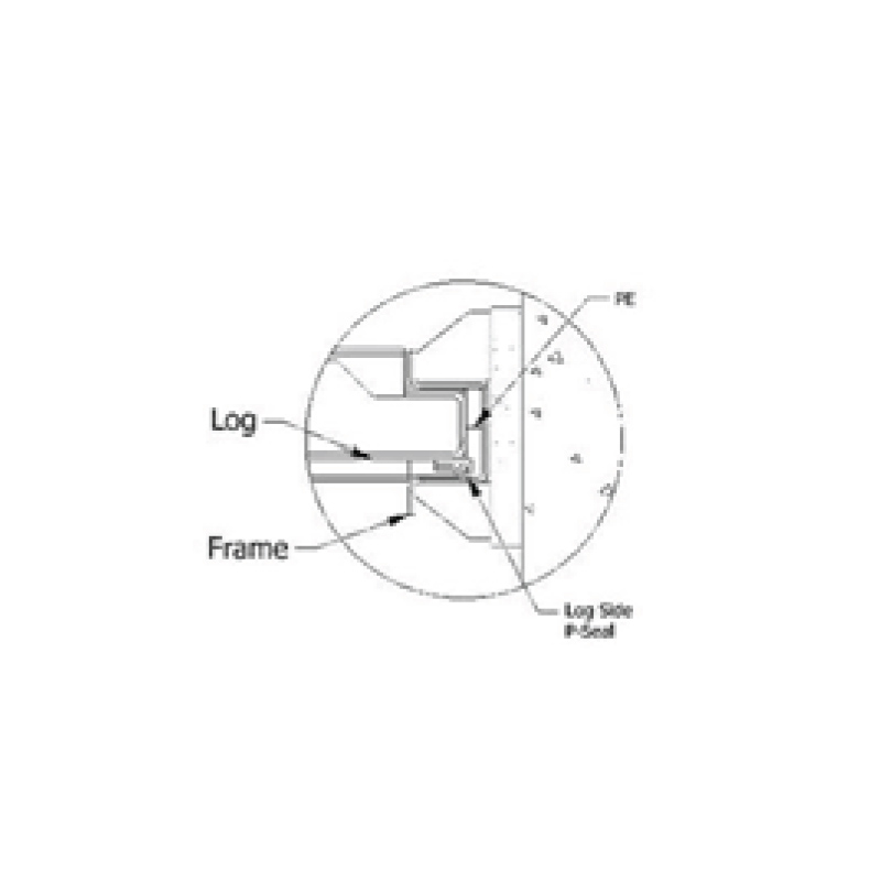
Side Design |
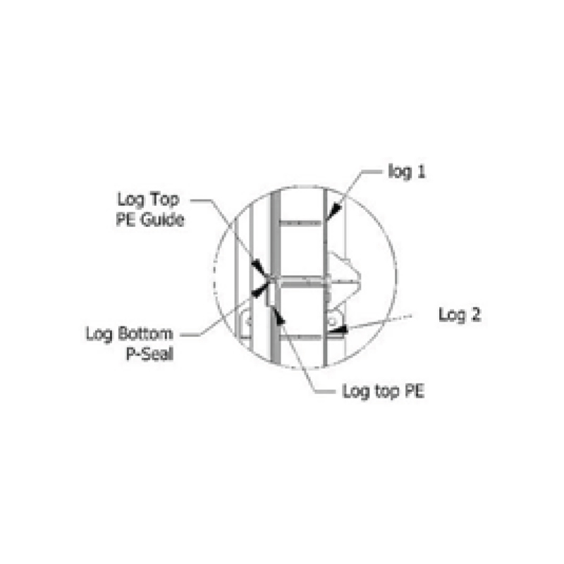
Intermediate Design |
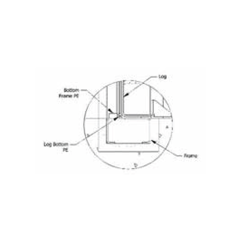
Bottom Design |
Lifting Beam :-
- The Lifting beam is built to automatically latch on to panel when lowered into the guide rail.
- The beam is released from the panel by a single tug on the rope tag line.
- Available in Stainless Steel and Mild Steel

Lifting Beam
